Sport Bikes banner

CO Adjustment (Explaination) and other ECU Fun

88K views 46 replies 21 participants last post by  sportrider_fz6  
#1 · (Edited by Moderator)
It's been a while since I last posted on this topic.

Background:
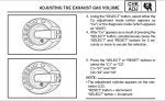
(Swiped from R6Messagenet.com - How-to: Richen or lean mixture without a power commander!)

So - picture the crisis - the EPA will randomly test a bike or 10 in the shipment, lots of highly-paid managers in a panic - we have to delay the shipping of the R6 for THREE MONTHS (a guess) and spend $19M (another guess) to fix this problem by having techs at the warehouse in the US tune (with an A/F sniffer and a wrench) the first 9000 bikes already on the container ships! And we can't schedule another test for EPA acceptance until JUNE!

So - the cry is to 'fix it in software!'. Some junior engineer cooks up a scheme - and his boss and the Architect for the supplier of the ECU go to Yamaha, hat-in-hand, and diffidently suggest a reuse of the C0 mode menu (after all, a menu only sets variables - what the variables are used to control can be changed) to tune the individual cylinders at idle. Just for the first bikes to be shipped - Yamaha will fix the cause of the problem on the factory floor for the next production run. This way, the techs in the warehouses don't have to disassemble the bikes - only download a new firmware image, then run the bikes at idle with an A/F lambda sensor hooked up.

Get it?

Or perhaps, it became cost-effective to ship the same firmware for the $600 race ECU but disable the timing features in software - a safe bet, since the PC-III was so wildly successful most owners would never stumble on the fuel-management curve menu on their own. And if they did, only some limited number of people would find out... this is acceptable, if the major tuneability were still disabled. Only a small percentage of the standard-off-the-shelf units needed to be intercepted from the manufacturing pipeline and have only a small change to the firmware - a bit toggled in flash (likely with a BDM/JTAG header, so not do-able mounted on the bike), then those few sold to the race community. And Yamaha would then have a different part number between the R6/FZ6 and R1.

See - to the vendor of the ECU, this is only mixing-and-matching of software modules to build the firmware load. I bet there's minimal at best difference in the hardware - and that's designed modular(ly) enough to let the same firmware run (with minor changes - flags enabled/disabled, hardware type bytes set just so) on a Road Star ECU or on a R1 ECU.

What I've Found:


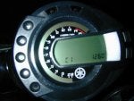
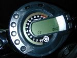
C1 controls the CO adjustments for cylinders 1 and 4
C2 controls the CO adjustments for cylinders 2 and 3
Ranges from +128 to -126 in increments of 1


The number is a factor that is used by the fuel injection system to compensate for manufacturing tolerances. It will be different for each cylinder. It is not a direct measure of the CO percentage of the exhaust gas. There is no way to predict the CO level from this number. A CO sniffer must be used on each header pipe (which means you must install a riv-nut on each pipe first to sample from). Then this adjustment is used to bring the CO levels as shown by the sniffer to specification (3-4% at idle)
Source --> Changing the FJR's CO Settings


Mixture is delivered by 36mm throttle bodies utilizing what Yamaha terms "group injection." The throttle bodies are grouped into two pairs consisting of the 1 and 4 cylinders and 2 and 3 cylinders. Each group of injectors will fire twice to deliver each of the cylinder's charges, or to put it another way, the amount of fuel needed for each cylinder's combustion stroke is divided into two injector bursts of 50 percent each.

For those who need to know even more, each injector's four jets fire on the compression and combustion strokes. By spraying when the intake valves are closed, the fuel has a little more time to atomize before being sucked into the cylinder. This more automotive style of injection should lower emissions, particularly when combined with the catalyst in the exhaust. According to Yamaha, this allowed the designers to leave off the vacuum slides utilized on the R6 while still maintaining rideability.
Background on above-- > http://www.superbikeplanet.com/2003-Sep/030909fz1.htm


Here is a link to a site that has done dyno graphs of changes made to the CO levels of an R6 Regolazione CO su centralina R6 2003


I don't know if anyone will want to read all this crap, but I needed some other opinions on what I have researched so far. :pisson

Later and more to come,
Zeb
 
#2 · (Edited)
This has been eating away at my brain since i got my F.I. FZ6. What the hell were the manuals talking in the R6's C1-C4 and the FZ6's C1 and C2? On my old bike (Suzuki Intruder 1400 2001, carbed v-twin) i got to play with my carbs and jettings and all that shit and the first thing my mechanic mentor taught me was that the front carbs jet is smaller than the rears (usually 2 #'s) due to that if the mixture is lean the piston runs hot. Since the front cylinder gets more air than the rear one you could run the front hotter and get a better response all trought the throtle range. Lean is good for taking off, rich is good for going FAZtER. So one rich and one fazt waz gud.

Needless to say carb tunning is hell and more of an art than a science (better results than FI though). That's why i got the FZ6. Now I stumble upon this CO shit.

I read all the info posted here and now it makes sence! C1, C2, C3, C4 on the R6 stands for cylinder 1 trough 4. On the FZ6 Yami grouped cylinder 1 and 4 under one setting and 2 and 3 under another. C1 and C4 are on the outside so they get more air and cooling than C2 and C3 so they are lean, for the same reason C2 and C3 are richer.

Proof, on my bike C1(c1&c4) was at -5 and C2(c2&c3) at 2.
The outer cylinders were leaner than the inner ones. This also explains why when i changed C2 on my bike i felt a difference on less that 25% throttle opening when acording to some pleople it shouldn't happen. Well it does and now I can sleep better having unraveled the CO misteries. Thanks dude!
BTW read the FZ6 manual now and it makes sence!
Suposed experts :pisson :lol
 
#4 · (Edited)
I care... That's why I posted :beer

Maybe everyone will chime in tomorrow... :lol

Good post FAZtER!!!! I hadn't thought of that one...

It may be a combination of the outer banks receiving more cooling allowing them to run leaner than the two inner banks running a tad bit richer to compensate for the added heat buildup. Maybe that coupled with the firing order of the bike?
 
#8 ·
nimms said:
maybe one of the italian folks on this site could look at the site with the charts...
not sure if i am missing something but it doesnt really look like messing with the CO settings made any difference in Horse power.

Thats because to do it correctly you would need an exhaust probe for the CO and unburnt gas levels. Then you could adjust it like a bean counter counting pennies, and that would give a couple extra ponies and faster/smoother revving.

If someone felt like getting the probe and putting holes into the exhuast header pipes to do it right, then they might notice the difference.
 
#9 ·
Lots of good reading here just alot to absorb at once but sounds like were onto something just like what KDK was saying we would have to have someone get a CO2 probe of some type so we can see it this actually helps then a dyno run or two also. Okay so whos gonna be the first to try this out :lol
 
#10 ·
That is easier said than done. First like KDK said you'd have to make a whole in each header to acuratelly measure CO leves. What some performance shops do is make custom headers for this. I just won a extra set of headers in e-bay though............ :rolleyes But i aint doing this, i think it's unecesary. Id be more interested in dyno runs to see a diference than CO levels. If you change the CO enough you will see a diference in the dyno charts. And if you really need to measure CO just do it were the cat pipe connects. :smokin <-----CO
 
#11 ·
If I can come up with a headpipe to put the holes in and weld the bungs too, I've already got the exhaust gas sensor. A buddy and I went in on one together a couple of years ago to tune our fourwheelers with. It works very nicely and does make a noticable difference when you get done. Anybody got a slightly damaged header they want to get rid of for cheep????
 
#12 ·
This is what I get from the graph below.

Image


The Green line represents a CO level of 0
The Red line represents a CO level of +50
The Blue line represents a CO level of -50

These were measured at 5% throttle position from 0 to 5000 RPM.

If you only look at the HP DIN (not SAE) vs RPM
(DIN is a measure of HP at rear wheel; SAE is a measure of HP at engine)
You will notice that where the A/F ratio is almost perfect (~14:1 @ 3920 RPM) the CO value of 0 (Green line) makes the most power at 33HP.

Now these aren't the greatest dyno graphs because they are taken at part throttle and we don't have the rest of the part and full throttle graphs to see the effects of the CO level change.

Based on what I saw on the dyno graphs and so ******* butt dyno time. I reset all my CO values to 0 (both C1 and C2). I am very (read VERY) happy with the results. Factory had me at C1 = -20 and C2 = -2. I tried uping both +3, +5, +7, +9, +11... etc to see if my butt dyno could tell any difference.

Something that may interest you guys and gals is that you can make adjustments to the CO values for C1 and C2 with the bike running.

Image


In this picture look at the 0 next to the C1. This is actually a Tach that displays 0 to 3000 RPM.


Hope this will get some intrest in this thread and have people post their butt dyno results. :cheers


Zeb
 
#16 ·
zeb said:
This is what I get from the graph below.

The Green line represents a CO level of 0
The Red line represents a CO level of +50
The Blue line represents a CO level of -50


Zeb

is this an acurate comparison as the stock settings are neither +/- 50.
also looking at this same chart why is looking at 3900rpm more or less meaningful than say 3100 or 3300-3700rpm.

im not trying to be a butt hook just trying to determine if this is worth the effort. Your ******* dyno results has me half tempted.
 
#17 ·
Yeah, You just enter CO mode (Hold down "Select and Reset" for about 8 seconds. Then press select to switch to CO mode from DIAG mode. Hold down "Select and Reset" again for 5 seconds. It will display C1 and pressing select will display C2)
Then fire up the bike normally. You will see the 0 on the display change to the idle RPM (Correction -- RPM displayed is 2000RPM max not 3000).

See the attached files...


Have fun guys and report back on butt dyno results :phatyo
 

Attachments

#19 ·
I agree nimms, The dyno graph is kinda crappy. It has lots of holes in the data (which I mentioned) No results from each setting (ie C1, C2, C3 and C4), no varying throttle positions, and why only sample to 5000RPM. These are the questions I have asked, but this is the only numerical data I have found to support anything that we are trying to do here.
I would really like for everyone to try and give some feedback so we can see if this really works.

Also, I have had an epiphany today about these CO level numbers. What if this adjustment does nothing to the fuel map, but makes an adjustment in the AIR injection valve for the Emissions system. Perhaps it dumps more or less air into the exhaust to dilute the PPM of CO for the bike to pass emissions testing.
Just an idea... I thought of it because when I changed both values to 0. I noticed it had less engine braking.

Later,
Zeb
 
#22 ·
zeb said:
Also, I have had an epiphany today about these CO level numbers. What if this adjustment does nothing to the fuel map, but makes an adjustment in the AIR injection valve for the Emissions system. Perhaps it dumps more or less air into the exhaust to dilute the PPM of CO for the bike to pass emissions testing.
Zeb
I looked at the Air Induction System part of the service manuals for both the FZ6 and the 2003 R6. Although the air cut-off valves are different part numbers on the two bikes they seem to operate in the same way on both.

AIR INDUCTION SYSTEM
AIR INJECTION
The air induction system burns unburned exhaust
gases by injecting fresh air (secondary
air) into the exhaust port, reducing the emission
of hydrocarbons.
When there is negative pressure at the exhaust
port, the reed valve opens, allowing secondary
air to flow into the exhaust port. The required
temperature for burning the unburned exhaust
gases is approximately 600 to 700 C (1112 to
1292 F).

AIR CUT-OFF VALVE
The air cut-off valve is controlled by the signals
from the ECU in accordance with the combustion
conditions. Ordinarily, the air cut-off valve
opens to allow the air to flow during idle and
closes to cut-off the flow when the motorcycle is
being driven. However, if the coolant temperature
is below the specified value, the air cut-off
valve remains open and allows the air to flow
into the exhaust pipe until the temperature becomes
higher than the specified value.

Unless the C1 - C4 settings on the R6 affect the individual reed valves, both the FZ6 and R6 air cut-off valves work on a pair of cylinders at a time : 1 & 2 and 3 & 4. I think FAZTER may by closer to the truth with his "compensate for higher temps in the middle cylinders" theory.
 
#23 ·
Oh, something else from the anecdotal evidence file : after I had upped the CO numbers by +9 each, I was on a group ride and the guys behind me said my bike was running rich because they could smell it.

The fact that the rpm counter associated with the CO settings only goes to 2000 suggests to me that this is for setting the CO levels at idle for emissions testing and not much else.
 
#25 ·
The dealership had to contact Yamaha to figure out what to do for my FZ when it kept sputtering, popping, and stalling. I told them about the possible TPS issue but Yamaha had them re-map it and use the exhaust probe. The bike has ran like a champ ever since. The idle is at 1300 rpm the acceleration is smooth and my pipes stopped blueing.
 
#26 ·
This is really interesting stuff you guys are posting up here. I have Akrapovics on my Fz6 and its never idled as smoothly as I'd like it to. So after months of doing nothing, i balanced the throttle bodies and messed around with the co. The figures I got when i opened up the CO menu on the tacho screen were C1= -22, C2=-6. After trying it out with different numbers (both plus and minus numbers) I settled on +10 for both C1 and C2. It now runs VERY smooth. When I took it out for a blast, the throttle response was so smooth and responsive! Like a different bike. BUT, should I have set the values for C2 lower than C1?
Thanx for the info guys.